It Started With a Hardware Limitation I have been using Quectel GNSS modules in my designs for a while. They are reliable, well-documented, and the support ecosystem is solid. But the module I had been using had one problem that I kept running into: no external antenna support . For most projects that is a minor inconvenience. For a marine vessel monitoring and control system , it is a non-starter. A vessel hull blocks sky view, antenna placement is critical, and the difference between a clean fix and no fix at all often comes down to whether you can mount the antenna where it actually has line of sight. An integrated antenna in a sealed enclosure below deck simply does not cut it. So I went directly to Quectel. The Conversation With Quectel I reached out through their official sample request channel. I was not expecting much — most component manufacturers have a standard process: fill out a form, wait, get a few uni...
I almost spend two days on this experiment and just found that the new concept in this experiment works well. But the problem comes when we think of current. The current that i get is two low to power on electronics.
The moving transformer concept is cool one to experiment. ;) (this message is for electronics dudes out there). I wound coil on the moving part(150 Turns) of the fan and wound another coil that will be fixed around the moving part(200 Turns). Then i gave PWM signal to the GATE of FET which is connected to the fixed coil, at the frequency of 20KHz.
I used FET because it is capable of high speed switching then transistors. Finally i got an AC voltage across the the moving coil(7.8 V) and then i connected an LED just to check the performance. Actually the concept works (Transfer voltage to an moving coil). Bad part is the current is too low and if i want to increase the current i need to wound think gage coil and this will become expensive for this kinda small projects. If you want to use this method for a big project, its ok to use..
I took some pictures of the experiments and you viewers have a look at it. For the propeller clock i will just skip this for some time and will do when i get an motor that can be tap out an a wire from the comunitator. This idea will be better for a propeller clock. So everyone enjoy pics..

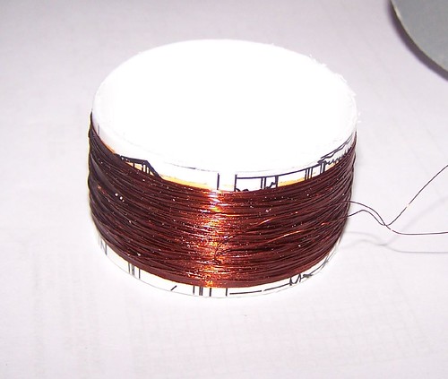
The moving part(Coil wound up to 150 Turns)

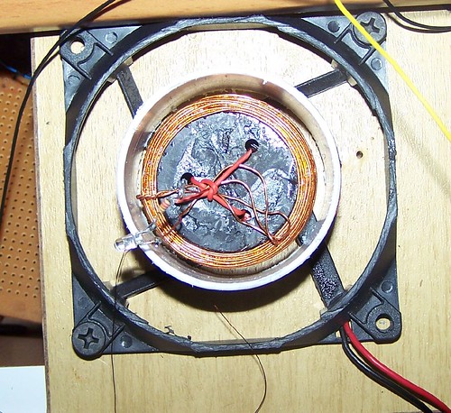
The fixed coil(200 Turns)

Fully assembled with a test LED

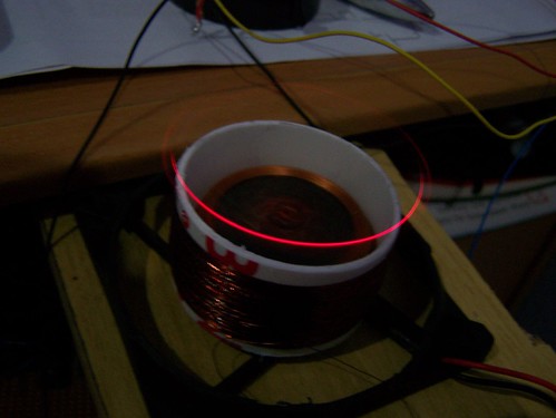
Test successful. See more pictures from flickr
The moving transformer concept is cool one to experiment. ;) (this message is for electronics dudes out there). I wound coil on the moving part(150 Turns) of the fan and wound another coil that will be fixed around the moving part(200 Turns). Then i gave PWM signal to the GATE of FET which is connected to the fixed coil, at the frequency of 20KHz.
I used FET because it is capable of high speed switching then transistors. Finally i got an AC voltage across the the moving coil(7.8 V) and then i connected an LED just to check the performance. Actually the concept works (Transfer voltage to an moving coil). Bad part is the current is too low and if i want to increase the current i need to wound think gage coil and this will become expensive for this kinda small projects. If you want to use this method for a big project, its ok to use..
I took some pictures of the experiments and you viewers have a look at it. For the propeller clock i will just skip this for some time and will do when i get an motor that can be tap out an a wire from the comunitator. This idea will be better for a propeller clock. So everyone enjoy pics..

The moving part(Coil wound up to 150 Turns)
The fixed coil(200 Turns)
Fully assembled with a test LED
Test successful. See more pictures from flickr
Comments