Custom ESP32-S3 development board — professionally manufactured by JLCPCB. A far cry from where it all started. It Started in a School Science Lab — Around 1998 Most people who get into electronics start with a kit, a tutorial, maybe a breadboard and some LEDs. I started by sneaking ferric chloride out of a school science lab to etch my first PCB. That was around 1998. I was living in the Maldives — a small island nation in the Indian Ocean — where there was no electronics supply chain, no maker community, no local PCB fab. Just a chemistry cabinet at school, a copper-clad board from somewhere, and a lot of curiosity. This post is about what the next 25+ years of PCB prototyping looked like from there. The early wins with proper chemicals, the years of improvisation when those chemicals disappeared, the real injuries, the failed boards, and finally — the moment JLCPCB changed ever...
I almost spend two days on this experiment and just found that the new concept in this experiment works well. But the problem comes when we think of current. The current that i get is two low to power on electronics.
The moving transformer concept is cool one to experiment. ;) (this message is for electronics dudes out there). I wound coil on the moving part(150 Turns) of the fan and wound another coil that will be fixed around the moving part(200 Turns). Then i gave PWM signal to the GATE of FET which is connected to the fixed coil, at the frequency of 20KHz.
I used FET because it is capable of high speed switching then transistors. Finally i got an AC voltage across the the moving coil(7.8 V) and then i connected an LED just to check the performance. Actually the concept works (Transfer voltage to an moving coil). Bad part is the current is too low and if i want to increase the current i need to wound think gage coil and this will become expensive for this kinda small projects. If you want to use this method for a big project, its ok to use..
I took some pictures of the experiments and you viewers have a look at it. For the propeller clock i will just skip this for some time and will do when i get an motor that can be tap out an a wire from the comunitator. This idea will be better for a propeller clock. So everyone enjoy pics..

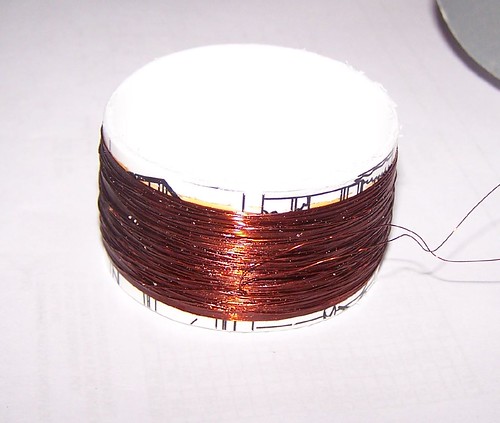
The moving part(Coil wound up to 150 Turns)

The fixed coil(200 Turns)

Fully assembled with a test LED

Test successful. See more pictures from flickr
The moving transformer concept is cool one to experiment. ;) (this message is for electronics dudes out there). I wound coil on the moving part(150 Turns) of the fan and wound another coil that will be fixed around the moving part(200 Turns). Then i gave PWM signal to the GATE of FET which is connected to the fixed coil, at the frequency of 20KHz.
I used FET because it is capable of high speed switching then transistors. Finally i got an AC voltage across the the moving coil(7.8 V) and then i connected an LED just to check the performance. Actually the concept works (Transfer voltage to an moving coil). Bad part is the current is too low and if i want to increase the current i need to wound think gage coil and this will become expensive for this kinda small projects. If you want to use this method for a big project, its ok to use..
I took some pictures of the experiments and you viewers have a look at it. For the propeller clock i will just skip this for some time and will do when i get an motor that can be tap out an a wire from the comunitator. This idea will be better for a propeller clock. So everyone enjoy pics..

The moving part(Coil wound up to 150 Turns)
The fixed coil(200 Turns)
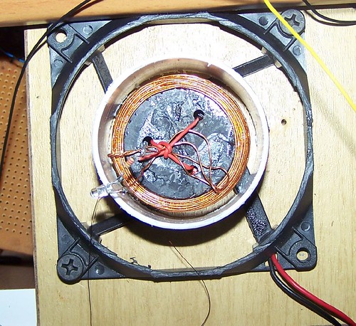
Fully assembled with a test LED
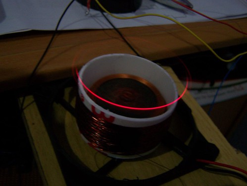
Test successful. See more pictures from flickr
Comments