Custom ESP32-S3 development board — professionally manufactured by JLCPCB. A far cry from where it all started. It Started in a School Science Lab — Around 1998 Most people who get into electronics start with a kit, a tutorial, maybe a breadboard and some LEDs. I started by sneaking ferric chloride out of a school science lab to etch my first PCB. That was around 1998. I was living in the Maldives — a small island nation in the Indian Ocean — where there was no electronics supply chain, no maker community, no local PCB fab. Just a chemistry cabinet at school, a copper-clad board from somewhere, and a lot of curiosity. This post is about what the next 25+ years of PCB prototyping looked like from there. The early wins with proper chemicals, the years of improvisation when those chemicals disappeared, the real injuries, the failed boards, and finally — the moment JLCPCB changed ever...
What is NMAP & use of it?
Basically NMAP is a free security scanner and a network mapper mainly used by system administrators, hackers , pentesters and etc. These are few use cases of NMAP and there are tons of ways to use NMAP.
- Finding hosts in the network
- ports used by hosts and its status
- Finding vulnerabilities
- Information on versions and OS used
Basic NMAP Scan
nmap -sP 192.168.1.0/24
Ping multiple host to check if the hosts are alive or not
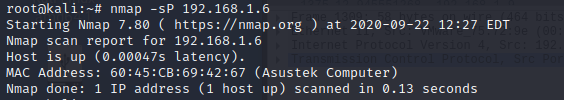 |
| Screen capture of scan |
TCP scan (full open scan)
nmap -sT 192.168.1.9This is a TCP connect scan. TCP connections are done with a 3 way
handshake
- SYN
- SYN-ACK
- ACK
This is otherwise called as full open scan
 |
| Screen capture of scan |
 |
| Wireshark packet capture |
Stealth Mode Scan (Half open scan)
namp -sS 192.168.1.9
This is known as SYN scan / Half open scan / Stealth scan
- SYN
- SYN-ACK
- RST
 |
| Screen capture of scan |
 |
| Wireshark packet capture |
OS detection scan
namp -O 192.168.1.6

With this command you can get which OS the system is running. Example: Windows, Linux, Android etc.
NMAP with OS detection, traceroute, host discovery and more
nmap -A 192.168.1.6 
This is aggressive scan and do not use these commands on unauthorized networks. From this command you can get version informations, OS detection , traceroutes and ports status etc..
NMAP Scripts
nmap --script exploit 192.168.1.6
With NMAP script can be run to check vulnerabilities, exploits and much more. Details of scripts listed in official NMAP page and full list of attributes details are listed on the page.
If you are in a linux box just type
man nmapOutput to a File
nmap -oN dump.txt 192.168.1.6You can dump all the scans using this method. So you can refer later.
Reading host from file
nmap -iL targets.txtIn Order to use this command you have to first create a file with list of targets as follows
192.168.1.6
192.168.1.2
192.168.1.8
Like the above you can enter a list of IP's to a file and save it. Then once you execute the command the scan starts by reading hosts from the file. This method is easy if you have multiple IP's or different subnets to scan.
Reference
https://explainshell.com/ - This website will explain the commands in details
https://www.guru99.com/tcp-vs-udp-understanding-the-difference.html - TCP vs UDP explained
Comments