
How to setup 2FA On Linux SSH Login

  This is a simple setup guide to enabling Two Factor Authentication (2FA) on Linux SSH login. I this article I wont go deep into setup and issues that I have faced when implementing this. First thing is first Update your system first. I have used Ubuntu 20.04 and it is always up to date. To enable 2FA you need to install google authenticator modules sudo apt install libpam-google-authenticator Configuration for PAM and SSHD Add the the following line to /etc/pam.d/sshd and After adding this line please restart the sshd services.  auth required pam_google_authenticator.so Go to /etc/ssh/sshd_config and check if the following line exist. Default value will be "no" so change it to "yes" to activate.  ChallengeResponseAuthentication yes Configuration for Authenticator In the terminal run google authenticator command It will ask few things to acknowledge by user. Details you can see from the below video. Once this part is done you are ready to use the 2FA in ubuntu. T

Dockerfile and Docker-compose

How to use Dockerfile?

This file contains user commands which will be needed to build an image. This is the simplest way that I can explain this. For more information please follow the Dockerfile reference guide

The following image shows a sample Dockerfile that I created to build an image with php. I will explain line by line.

  1. FROM php:7.4.4-apache - This is where you define what image you will be using to build a custom image
  2. COPY site1/ /var/www/html - This is will copy the local path content to remote path (to container)
  3. EXPOSE 80 - This is where you define which port should be exposed


After creating a Dockerfile now you can build the image. 

docker build -t somename #this command is to build an image with the given tag name


After creating the image you can run docker images to view if the created image exists.


If you want to check if the image is created or not just run this command. docker images, this will show all the images created.

As you have seen the image name shows phptutorial , which i used as a tag while creating the image.

Now you can run the image to see if it works or not. 
You can run either way you prefer. here is the commands I use to run the container
docker run -i --rm --name phpTut -p 80:80 phptutorial


After a successful run when I brows in to the docker host, it shows the content in the php file that I kept in site path.

So everything works fine and lets go ahead with the interesting part. First stop the container by docker stop command.

docker-compose

In simple terms its an tool to run multiple container docker application. For example you have a php and a MySQL container and you want to run from a single command, docker-compose is the best way. Its an orchestrator and you have to define every thing on an YAML file.

The following image shows the docker-compose.yml file that I created for this post. You can do much more and this is just a basic one and please do refer the documents of docker for more.  


Now you can run with docker-compose up command.


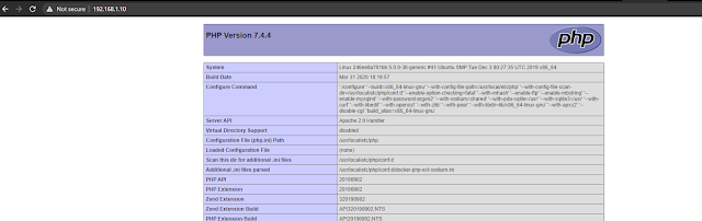
From the video you can see I am running both php and a mysql container from a single command. Below image shows the phpinfo file which is in the php container. How cool is this. you can do many fun stuffs and experiments while you prototyping and you can do more complex things. Lets run a docker ps command to check which containers are running.


Clearly its showing that php and mysql containers are running with its own exposed ports. 


lets conclude this topic now. I hope this would help someone. Please do subscribe for more and in future more docker tutorials will come. Lets hope for the best. Thank you all for the support.


Comments

mabellaqueenan said…
Casino games and slots - Review - BonusBetsSites777.com
Casino Games - Play the most exciting slots and casino 코인갤 games. ➤ Casino Games & More 벳썸 도메인 at BonusBetsSites777.com. Claim 페이 백 먹튀 Welcome 복불복 룰렛 Bonuses ✓ Free 강원랜드후기 Spins for Desktop & Mobile.

Popular posts from this blog

Clover Display M302 hack

Its been a while i have this LCD and today i thought of connecting the LCD display to Arduino. Unfortunately i could not found any pin outs of this from any where and from the manufacture. Actually this is very old model which i got from old FAX machine and this display is a very cheap from online sources. Clover Display M302 PCB Ver 1.0 (16x2) which has 10 pin flat cable. After researching for a while from the internet i have seen in many forums people are asking for help on how to connect it and what is the pin configurations? so i thought of helping them as well as my self at the same time. After going through some of my old collections of Russian data of displays and things i found a basic diagram of how 10 pin LCD display configuration.  PIN1   - VSS PIN2   - VDD PIN3   - CONTRAST PIN4   - RS PIN5   - R/W PIN6   - ENABLE PIN7   - DB4 PIN8   - DB5 PIN9   - DB6 PIN10 - DB7 I tried these configurations and wired up to the arduino with the LCD sketch

SIMCOM SIM900A fixed

Since everyone is interested in this post and lots of request comes to get the firmware, i have put a link so that everyone can download it easily. SIMCOM 900A firmware Its been a while that i was trying to fix the SIM900A GSM module. This module support local GSM band but after some researches it was concluded that it is carrier locked :(. After long conversion of days to actual chip manufacture SIMCOM, they told it can be fixed by updating its firmware to latest original version but unfortunately they don't provide firmware to small parties. I never stop trying to get the firmware and SIMCOM again replied, this time they said contact local SIMCOM supplier and request for firmware. But this little Maldives don't have SIMCOM or any electronics manufacturer. So i contacted my friend coody from NOA LABS/Smart prototyping (a friend in china) and told him to help me. I explained him what to do so he can communicate with SIMCOM in china. Finally he sends and email saying that

ESP8266 + DS18B20 Temperature sensor sends data to Thingspeak.com

Its been a while i was searching for a cheap wifi module and with the help of smart-prototyping.com , i was able to get a module almost less than USD 5. To connect the module to breadboard for prototyping, i made a small jig to interconnect with the board easily. So i can wire up the device and interface anything to GPIO's. Be careful with the module cause the device it powered with 3.3V and both UART side levels will be 3.3V so i recommend to use a FTDI converter with 3.3V level select.(one i used can select 3.3 and 5 volts) if you connect 5V the module will fry up. If you have 5V or 12V supply to power up the module i suggest to use LD1117V33 to make 3.3V. The stock Firmware in the ESP8266 supports AT commands and for communicating with this need an micro-controller like Arduino. But i want to make a simple solution for that without using external micro-controller. NodeMCU firmware was the best thing i found. To upload the NodeMCU firmware please do a google sear